
Making an antenna to listen to the ISS #
Why? #
As F4NIQ, I now want to deepen my understanding of radio frequencies — and what better way than trying to receive a signal from space?
The International Space Station (ISS) transmits on the 145.800 MHz downlink frequency (2m amateur band), broadcasting APRS packets and occasional voice communications. With the right setup, receiving it is very much within reach of a home station.
What you need #
To receive a satellite RF signal, you need three things:
- A software-defined radio (SDR) — converts analog radio waves into digital samples a computer can process
- An antenna — a simple dipole technically works for the ISS, but a directional Yagi gives noticeably better results
- Decoding software — SDR++, SDR Angel, or GNU Radio are all solid choices
Software-defined radio #
In the early days of radio, each receiver was built around a fixed demodulation circuit in hardware. A software-defined radio replaces most of that hardware with a wideband analog-to-digital converter and moves the demodulation into software. This means a single device can cover an enormous frequency range and switch between AM, FM, SSB, or any other mode without touching a screwdriver.
SDRs range from ~$25 RTL-SDR dongles to professional units costing several hundred dollars. For this project I’m using a HackRF One.
HackRF One — key specs (source)
- Operating frequency: 1 MHz – 6 GHz
- Half-duplex transceiver (receive and transmit)
- Up to 20 Msps (million samples per second)
- 8-bit quadrature samples (I and Q)
- Compatible with GNU Radio, SDR#, and more
- Software-configurable RX/TX gain and baseband filter
- SMA female antenna connector
- USB 2.0 powered, open-source hardware
Choosing an antenna #
Three parameters matter when picking an antenna:
1. Gain #
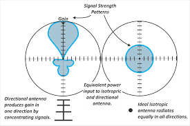
Gain measures how much an antenna concentrates radiated power in a preferred direction, expressed in dBi (decibels relative to an isotropic radiator). Higher gain means stronger signal in that direction — but always at the expense of coverage elsewhere.
2. Directionality #
An isotropic antenna radiates equally in all directions (a perfect sphere). Real antennas trade that omnidirectionality for gain. A Yagi antenna is highly directional: most of its energy (and sensitivity) is focused into a narrow lobe. The diagram below illustrates the difference.
3. Polarization #
Radio waves are electromagnetic: an oscillating electric field and a magnetic field, perpendicular to each other and to the direction of travel. The orientation of the electric field defines the polarization.
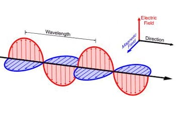
For the best signal, your antenna’s polarization should match the transmitter’s. The ISS uses vertical linear polarization for its 2m APRS downlink, so a vertically-oriented dipole or Yagi works well. Circularly polarized antennas (like a helix) are even more forgiving of the ISS tumbling overhead and are worth considering for a more advanced build.
Building a tape-measure Yagi #
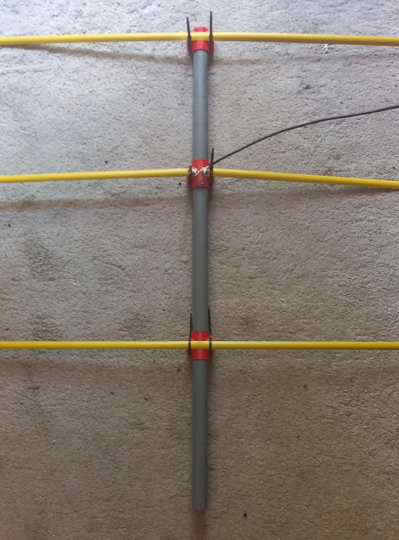
A Yagi-Uda antenna consists of three types of elements mounted on a common boom:
| Element | Role | Length (2m band) |
|---|---|---|
| Reflector | Reflects energy forward, sits behind the dipole | 1005 mm |
| Driven element (dipole) | The only element actually connected to the feedline | 997 mm |
| Director(s) | Narrows and focuses the beam forward | 951 mm |
The reflector is slightly longer than the driven element; directors are slightly shorter. This asymmetry is what creates the directional lobe.
Here’s the finished antenna — built with a tape measure for the elements (cheap, rigid, and easy to cut) and a broom handle as the boom:
Why a Yagi for the ISS?
The ISS passes overhead in roughly 10-minute windows at elevations that can reach 80°+. You’ll need to point (track) the antenna across the sky manually or with a rotor. For a first attempt, manually tracking works fine — the pass is slow enough to follow by hand.
Useful links and calculators #
- Tape-measure Yagi build guide — DigiKey
- Tape-measure antenna on Instructables
- Yagi-Uda element length calculator — changpuak.ch
- ISS APRS frequency and schedule — ARISS
- Track the ISS live — Heavens-Above
What’s next #
With the antenna built and the HackRF connected, the next step is tuning SDR++ to 145.800 MHz, setting the mode to FM narrow (bandwidth ~15 kHz), and waiting for the ISS to rise above the horizon. A successful pass sounds like a burst of digital chatter — those are APRS packets. Decoding them is the subject of part 3.